MAX7219 Led Dot Matrix Module 8x8 LED Display For Raspberry Pi Arduinos VariousProduct Description:
The MAX7219 is an integrated serial input/output common cathode display driver that connects a microprocessor to an 8-bit, 7-segment digital LED display, as well as to a line graph display or 64 individual LEDs. It includes an on-chip B-type BCD encoder, a multi-scan loop, a segment word driver, and an 8*8 static RAM to store each data. Only one external register is used to set the segment current of each LED.
A convenient four-wire serial interface allows connection to a general-purpose microprocessor. Each piece of data is addressable and can be updated without rewriting all the displays. the MAX7219 also allows the user to choose to encode or not encode each piece of data.
The device includes a 150µA low-power shutdown mode, analogue and digital brightness controls, a scan-limit register that allows the user to display 1-8 bits of data, and a detection mode that allows all LEDs to be illuminated.
Only 3 IO ports are needed to drive 1 dot matrix! Flicker-free dot matrix display! Supports cascading!
Module parameters:
1. A single module can drive a 8 * 8 common negative dot matrix
2. Module operating voltage: 5V
3. Module size: length 3.2cm X width 3.2cm X height 1.3cm
4. With 4 fixed screw holes, hole diameter 3mm
5. Module with input and output interfaces, support multiple modules cascade
Wiring instructions:
1. The left side of the module is the input port, the right side is the output port.
2. When controlling a single module, you only need to connect the input port to the CPU.
3. When multiple modules are cascaded, the input of the first module is connected to the CPU, the output is connected to the input of the second module, the output of the second module is connected to the input of the third module, and so on...
Take 51 microcontroller as an example:
VCC → 5V
GND → GND
DIN → P2.0
CS → P2.1
CLK → P2.2
Payment:We only accept your Address,Please Make sure it\'s right.
The items you ordered will be shipped out in 2 business day by Air Mail when your payment is clear. Terms of Sale:If you are not satisfied with the item, please contact with us.We will offer Full Refund to you when we receive your returned item.
Any problem, please feel free to contact with us. Shipping We ship to your or Paypal address. Please make sure your and Paypal address is correct before you pay. Contact us / response We care about our valued buyers, if you have any questions, our Customer Service staffs will be very glad to help you. We try our best to reply to your emails as soon as possible, however, due to high volume of daily incoming emails and time zone difference, we may not be able to reply your emails immediately. Please allow 24 business hours for us to response.
When you click on links to various merchants on this site and make a purchase, this can result in this site earning a commission. Affiliate programs and affiliations include, but are not limited to, the eBay Partner Network.

 3Pcs MAX7219 8X8 Dot Matrix LED Display Module 5V MCU Control MAX7219 8 * 8 LED$15.20
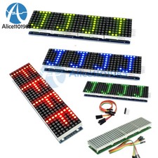 MAX7219 4 In 1 LED Display Microcontroller+5P Line Dot Matrix Module For Arduino$5.61
 2pcs 4 in 1 matrix 8x32 green led display module max7219 32x8 Arduino Raspberry$19.64
 Blue MAX7219 LED Dot Matrix 8 Digit Digital Tube Display Control For Arduino$2.51
 MAX7219 Led Dot Matrix Module 8x8 , 8x32 LED Display For Raspberry Arduinos Pi$18.78
 MAX7219 LED Display Dot led Matrix MCU Control Module for Arduino Raspberry Pi$8.23
 MAX7219 LED Dot Matrix 8-Digit Digital Tube Display Control Module For Arduino$10.04
 MAX7219 RED dot matrix 8x8 8*8 led display module for Arduino DIY Raspberry pi$2.99
 www.userbars.org














