EQUIPMENT IDENTIFICATION & SPECIFICATION SHEET
1. EQUIPMENT IDENTIFICATION
• Equipment Name: Generac H-100 Digital Control Panel & Enclosure Assembly
• Manufacturer: Generac Power Systems, Inc.
• Enclosure Base Stamped Part Number: 0F1826E
• Controller Logic Board Stamped Part Number: 0F2815 REV G
• Production Date Code: 0643 (Manufactured 43rd week of 2006)
• Related Generac Service / Assembly Numbers:
- 0F28150SRV (H-Panel Logic Module Service Kit)
- 0F5763 / 0F57630SRV
- 0G4140 / 0G4140E (Outer Bezel & Housing Face)
• NATO Stock Number (NSN): 6110-01-574-8848
- Federal Supply Class (FSC): 6110 (Electrical Control Equipment)
- Item Name: Control Panel, Power Distribution / Generator Set
• Compatible Systems: Generac commercial and industrial liquid-cooled standby
generator sets (typically 25 kW through 150 kW+ diesel, natural gas, and LP units).
2. INCLUDED SUB-ASSEMBLIES & MODULES
• Front H-Panel User Interface:
- Dual 4x20 character backlit liquid crystal displays (LCDs).
- 7-button sealed tactile navigation keypad.
- 3-position keyed mode selector switch (AUTO / OFF / MANUAL).
- Red twist-to-release Emergency Stop (E-Stop) push button.
- High-output piezoelectric audible alarm sounder.
• Internal Cabinet Components:
- OEM Open-Frame Battery Charger Board: Mounted on aluminum bracket at bottom right.
- Sensing / Potential Step-Down Transformer: Bracket-mounted at upper right.
- DIN Rail Relay & Fuse Block: Center rear backplate.
- Terminal Screw Strip (TB3): Wired with original factory circuit jumpers.
- Complete Internal Wire Harness: Dual modular connectors intact to logic core.
• Rear External Equipment:
- Finned Aluminum Voltage Regulator / Heat Sink Module (top right rear).
- Heavy-Duty Starter / Slave Solenoid Relay with rubber terminal boot (bottom right rear).
- Heavy-Duty Loomed Wire Pigtails: Engine and AC sensing bundles with legible
factory stamped circuit numbers (e.g., 0, 11, 22, 33, 183).
3. TECHNICAL SPECIFICATIONS
• Logic Board Operating Voltage: 12V DC nominal (battery system supply)
• Auxiliary Line Input: 120V AC (powers internal charger circuitry, internally fused)
• Display Architecture:
- Left Display: AC metering interface (Phase, Volts, Amps, Hz, kW).
- Right Display: Operating status, fault messages, and diagnostic alarm log.
• Sensor Inputs & Interfaces:
- Analog Inputs: Oil pressure sender, coolant temperature sender, fuel level.
- Digital Fault Inputs: Low fuel pressure, emergency stop, low coolant level switch.
- Alternator Telemetry: True-RMS 3-phase AC voltage sensing, current transformer (CT) inputs.
- Communications: RS-485 serial communication bus for ATS and GenLink telemetry.
• Enclosure Construction: Heavy-gauge powder-coated steel with hinged door and weather seals.
• Total Assembly Weight: ~15 lbs
4. STANDARD OPERATIONAL USES
• Primary Commercial Generator Control: Serves as the complete brain, monitoring
utility mains, executing engine start sequences, controlling governor actuator,
and signaling the Automatic Transfer Switch (ATS) during utility outages.
• Live Electrical Parameter Monitoring: Continuously calculates and reports
true-RMS phase-to-phase and phase-to-neutral AC voltage, amperage draw, system
frequency (Hz), and running electrical load in kW.
• Engine & Alternator Protective Tripping: Safely shuts down the prime mover upon
detecting critical engine anomalies (low oil pressure, high water temp, engine
overspeed, emergency stop activation, or low fuel supply pressure).
• NFPA 110 Compliance & Event Logging: Maintains time-stamped chronological records
of emergency stop trips, comm dropouts, and maintenance intervals for life-safety
power system recordkeeping.
5. THEORETICAL & EXPANDED USES
• Microgrid / Hybrid Power Management: Repurposing the RS-485 serial port and
kW load metering as a supervisory controller for custom off-grid battery/solar
inverter installations to manage automated generator load-shedding and backup dispatch.
• Engine Dynamometer / Dyno Test Stand: Utilizing the self-contained cabinet,
wiring loom, and analog/digital sensor inputs to build a stationary testing console
for rebuilt industrial engines.
• Remote Pump Station / Irrigation Controller: Leveraging the NEMA-style steel
enclosure, 12V DC logic core, and onboard fault shutdowns to control stationary
diesel or gas agricultural pump systems.
• Vocational Training Bench: Serving as an interactive technical training platform
to instruct generator technicians on 3-phase diagnostics, fault clearing, and ATS
serial communication troubleshooting.

When you click on links to various merchants on this site and make a purchase, this can result in this site earning a commission. Affiliate programs and affiliations include, but are not limited to, the eBay Partner Network.

 Generac Nexus Controller Generator Generac 0H7668C Nexus Control Panel$400.00
 Generac Smart Management Module SMM 0068730 Load Shed Module 006873-0$60.00
 Direct Fit Transfer Switch Module For Generac 100A ATS Fused Board Smart Control$59.99
 A0004499959 Automatic Transfer Switch ATS Control Module for Generac 100/200A$68.89
 GENERAC GENERATOR 10 WIRE CONTROL CABLE (40-200 Feet) SAVE MONEY EASY WIRING$99.86
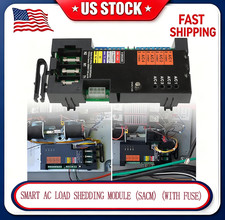 Direct Fit ATS Control Module Fit For Generac 100A 200A Switch Overload Shed$59.99
 Generac H-100 Control Panel Complete Box 0F2815 0F1826E Charger Tested OEM$1,299.99
 Generac 100Amp Automatic Transfer Switch ATS Fused Control Module SACM$145.60
 www.userbars.org













