16Bit AD7606 Module 8Channel Synchronization Sampling AD Module Direct Storefront Catalog Record16Bit AD7606 Module 8Channel Synchronization Sampling AD ModuleU.S. Shipping Contiguous StatesPrompt Dispatch Secure Packaging30-Day Returns Portal CareProtected Buy Managed PaymentsProduct Overview
1, using high-precision 16-bit chip AD7606
2,8 analog inputs. 1M ohm impedance.[No negative supply, there is no front-end analog amplifier can be connected directly to the sensor output]
3, the input range of plus or minus 5V, plus or minus 10V. By IO control.
4, Resolution 16.
5, the maximum sampling frequency sampling rate of 200ksps.
Supports eight sampling settings file (which can effectively reduce the jitter)
6, built-in for benchmark
7, a single 5V power supply
8, SPI Interface, or 16-bit bus interface. Interface IO level can be 5V or 3.3V.
We AD7606 module factory default is 8080 parallel interface.
If SPI interface mode, you need to modify R1 R2 resistor configuration.
Parallel Mode Jumper: R1 floating (not stickers), R2 10K resistor paste
SPI interface mode jumper: R1 stickers 10K resistor, R2 floating (not stickers)
AD7606 configuration is very simple, it has no internal registers.
Range and over-sampling parameters are controlled via an external IO.
Pulse frequency sampling rate provided by the microcontroller or for DSP control.
AD7606 must use a single 5V supply.
Level communication interface between the AD7606 and SCM controlled by VIO pin.
That VIO power supply must be connected to the microcontroller can be 3.3V can also be 5V.
[Module Pin Description]
OS2 OS1 OS2: a combination of state selection oversampling mode.
000 means no oversampling, the maximum sampling rate of 200ksps.
001 represents two times oversampling, which is the hardware inside collected two samples averaging
010 represents four times oversampling, which is the hardware inside collect four samples averaged
011 represents eight times oversampling, which is the hardware inside collected eight samples averaged
100 represents 16 times oversampling, which is the hardware inside collected 16 samples averaged
101 represents 32 times oversampling, which is an internal hardware averaging collected 32 samples
110 represents 64 times oversampling, which is the hardware inside collected 64 samples averaged
Oversampling ratio is higher, the longer For ADC conversion time, the lower the maximum sampling frequency can be obtained.
CVA, CVB: AD conversion start control signal channel 1-4 decision CVA, CVB decided 5-8 channels.
Two signals can stagger a short time, in general, can be CVA, CVB parallel together.
RAGE: Select the range of 0 means plus or minus 5V, 1 indicates negative 10V.
RD: Read signal
RST: Reset signal
Busy: Busy Signal
CS: chip-select signal
FRST: first a channel samples indicating signal
VIO: communication interface level
DB0 - DB15: Data Bus
[16 parallel mode wiring diagram --- AD7606 also supports 8-bit bus mode, see the AD7606 data sheet
MCU side AD7606 module
GND
When you click on links to various merchants on this site and make a purchase, this can result in this site earning a commission. Affiliate programs and affiliations include, but are not limited to, the eBay Partner Network.

 AD7606 Data Acquisition Analog to Digital Conversion ADC Module 16Bit 200KSps $39.44
 AD7606C-16 Data Acquisition Module 16-Bit 1Msps DAQ Supports 4CH Differential m1$99.75
 16Bit AD7606 Module 8 Channel 8CH Synchronization Sampling AD7606 Data$38.58
 AD7606C-16 Data Acquisition Module 16-Bit 1Msps DAQ Supports 8 Single-Ended$101.00
 AD7606 Data Acquisition Analog to Digital Conversion ADC Module 16Bit 200KSps $37.21
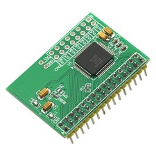 16Bit AD7606 Module 8Channel Synchronization Sampling AD Module$28.45
 PZ7606 PZ-AD7606 Synchronous Sampling ADC Module AD7606 8CH 16-Bit 200KSPS ADC$58.90
 Upgraded AD7606 AD Data Acquisition Module Board 16-bit 8-channel Sampling200KHz$31.44
 www.userbars.org














